Here are all the solutions to plug your SRT pedals. Two philosophies: connect the pedals to your steering wheel, or connect the pedals directly to the computer.
Table of contents
The vast majority of pedal sets use potentiometers. As the accelerator is based on a potentiometer, and the hydraulic pressure sensor also behaves like a potentiometer, you can connect this pedal sets to most of the steering wheel bases (logitech, Simucube, Thrusmaster…).
Alternatively it can be connected to a Leobodnar or Arduino card which is then connected to the PC via a USB cable.
1) LOGITECH (G27, G29, G920…)
You can connect the SRT pedal set to a G27 or G29 steering wheel. To do so, use a VGA male connector with the following pins:
1 – Ground (0v)
2 – Accelerator
3 – Brake
4 – Clutch
5 –
6 – VCC (+5v)
7 –
8 –
9 – VCC (+5v)
2) SIMUCUBE 1
The pedals can be connected to the X11-upper port. See details on the Simucube documentation.
Pin 1 is the rightmost one. A RJ45 (8P8C) cable must be used.
1 – Brake
2 – Throttle
3 –
4 – VCC ( +3,3V)
5 – Clutch
6 –
7 –
8 – Ground (0V)
3) SIMUCUBE 2
There is a “SC accessory port” on which there are pins to connect pedals, it’s female vga db15.
See the documentation available here. You can use this type of male connector. The pins you are interested in :
2 – Ground (0V)
6 – Throttle
7 – Clutch
8 – VCC (5V)
13 – Brake
15 – Ground (0V)
4) ARDUINO
If you don’t want to plug the pedals into your steering wheel, using an arduino card is the cheapest solution. The following code allows you to manage from one to three pedals. It only works with Arduino Leonardo and Micro cards (fitted with ATmega32u4 CPU). The required libraries are included in the code.
5) LEOBODNAR
This adapter allows you to connect the SRT pedals without having to manipulate a code. Indeed, Leobodnar provides an easy to use software that allows to calibrate the pedals.
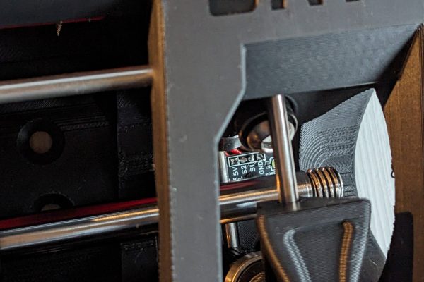
I created a junction box: a male VGA connector on one side, and three output cables (diameter AWG22, it’s the one indicated in the pedals stroke list. There is an anti-tearing system that ensures reliable operation. The 3D files are on Thingiverse. The male connector can be ordered here on Amazon, or Aliexpress.
6) THRUSTMASTER
The Thrustmaster T-GT, T300, T150, TS-XW, TX and TMX steering wheels are connected to the pedal sets though an RJ12 6P6C (6-wire) cable. If you don’t know where the 1 is on your cable, look at the color codes on Google.
1 – Brake
2 – Throttle
3 – Clutch
4 – VCC ( +5v)
5 – Ground ( 0v)
6 – Ground ( 0v)


You could make a GitHub public repository with the software for the pedals.
I think you misstyled – for =
Where is the problem with the code ? 🙂