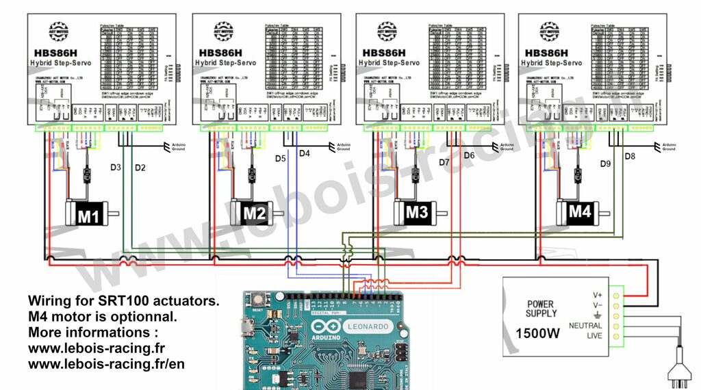
The wiring is quite simple. Each driver is controlled by two wires : pulse and direction. Once the driver received a “pulse” signal, the motor will moves a step.
If you have three actuators instead of four, you just have to not wire the fourth motor. The “direction” signal indicates in which way the motor will turn. So we need two wires between each driver and the Arduino :
| Driver HBS86H | Arduino UNO |
| Pulse + (M1) | D2 |
| Dir + (M1) | D3 |
| Pulse + (M2) | D4 |
| Dir + (M2) | D5 |
| Pulse + (M3) | D6 |
| Dir + (M3) | D7 |
| Pulse + (M4) (if using 4 actuators) | D8 |
| Dir + (M4) (if using 4 actuators) | D9 |
Each Pulse- and Dir- pins are linked to the Arduino ground.
Each driver is linked to the power supply by two wires. AC1 goes to +, and AC2 goes to -.
WARNING THE DRIVER SWITCHES MUST BE POSITIONNED AS FOLLOWED (for driver v3):
| Switchs | Position |
| SW1 | OFF |
| SW2 | OFF |
| SW3 | ON |
| SW4 | ON |
| SW5 | OFF |
| SW6 | OFF |
| SW7 | OFF |
| SW8 | OFF |
The motors are wired to the drivers by 4 wires :
| Driver HBS86H | Nema 34 Motor |
| A+ | Black |
| A- | Red |
| B+ | Yellow |
| B- | Blue |
Position encoders allow to detect the position of the motors, that is used to correct the position if needed. Each encoder is wired by 6 wires :
| Driver | Encodeur |
| PB- | Jaune |
| PB+ | Vert |
| PA- | Noir |
| PA+ | Bleu |
| VCC | Rouge |
| Ground | Gris/blanc |
Here is the full wiring schematic. Once again, the most important thing is to correctly set the driver’s switches. If not set properly, the actuator could get damaged by exceeding the maximum travel.
Once the wiring is done, you can link the Arduino to FlyPT and check if is works without the motor mounted on the actuators.