Load cell are the Holy Graal of Sim Racing. So let’s see how it works, and what it takes to use them.
1. What is a load cell
Load cells come in many shapes, and with different wirings.
But the basic is the following : you run wires along a metal part. When applying a load on this part, the part will deform a little bit, making the wires a little bit longer.
And the longer the wire, the higher the resistance.
And the deal is to measure the resistance delta by measuring the voltage difference. Obviously, the difference will be minimal, so we need an amplifier to measure that tiny difference (about some mV).
Load cells usually comes with three or four wires. We won’t get into details but with three wires, you measure one resistance delta, and with four, you measure two resistances deltas, so it will be more accurate.
As said, loadcells comes with different shapes, but also load ratings. You don’t want to put a 500kg load on a 1kg kitchen scale load cell… You will probably bend the load cell.
By the way, you really want to use short shielded wires between the load cell and the amplifier.
Now that you are aware of all of this, let’s get into the amplifier part.
2. Load cell amplifiers : digital or analog ?
The other thing you want to take care of is : do you want a digital or an analog output ?
With an analog output, your load cell will behave like a potentiometer. I would say that it’s the easiest way to use a load cell. The main downside is that the resolution depends on the ADC (analog to digital converter) you use. By example, Leonardo Arduino’s come with a 10 bits ADC (0 to 1023 points), that isn’t very high (high end pedals usally use 12 bits to 16 bits resolutions).
With digital amplifiers, the circuit and the code will be more complex. They usally requires at least two wires (beside 5v and ground wires) : one for the clock, that will synchronise all the components, and one for the data, that will actually send the data… You will also probably need a specific library (if you use an Arduino or a programmable board). With digital amplifiers, you want to check if the refresh rate is high enough.
3. Gain
The main parameters with amplifiers is the gain. As said before, we try to measure little variances in resistance, that will be seen as voltage variances. Let’s say that the delta between no load and maximum load on your load cell introduces a 1 mV delta. You will need to set the gain to 5000 to use the whole Arduino ADC range (5000*1 mV =5000 mV = 5V).
There is generally two ways to set the gain, that depends on the amplifier you use :
- Resistance based : the gain depends on the resistance between two pins. You want to use a potentiometer to easily adjust the gain. You will also find the gain formula in the datasheets.
- Software based : the gain is adjusted directly by the code. You find it with digital amplifiers most of the time.
4. Some common amplifiers
analog :
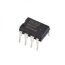
INA122 and INA129 are very cheap amplifiers. The gain is set by putting a resistor between pins 1 and 8 (see the datasheet here).
But be really carefull with the wiring as there is no security. I fried many of them due to wiring issues. You can find the 129 with a complete PCB like this one.
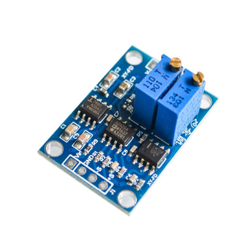
AD620 : similar to INA12x but you will find that kind of boards that are more complete, and comes with gain potentiometer and offset potentiometer (to tare the readings). Datasheet here.
digital :
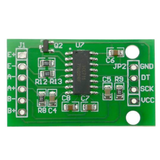
HX711 is the only one you will find. The problem is that the refresh rate is quite low (80 readings/sec). Datasheet here.
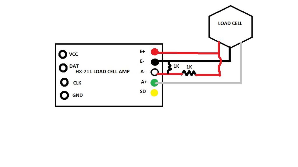
5. 3 or 4 wires load cell wiring
When you use a 3 wires load cell, you want to build a circuit that makes that 3 wires LC looks like a 4 wires LC by using a half bridge. In short it create the 2nd resistance variation, that will entirely depends on the first one.
You can also combien two 3 wires load cell to act as a single 4 wires.
6. Arduino code
Here you can think Arduino code that are working out of the box. Your arduino will be recognized as a joystick, and you can use it directly in game. It requires a Atmega 32U4 based arduino (Leonardo or Micro by example). So it won’t work with a Uno. All the libraries are included.
Too be added
Why do you think 80 SPS is not enough for brake pedal? That is 0.0125s = 12.5 ms, I doubt that this makes any difference for the reaction times.
Did you do any measurements to prove that this is too slow for the brake pedal?
You can see in the ingame gauges that it is too slow.
I used a load cell brake peddle connected to a beta innovations controller board with a incremental encoder for the steering and absolute encoder for the throttle back when rfactor was new release.
It was sensational. pity betta innovations is gone
Man I seriously need this code!